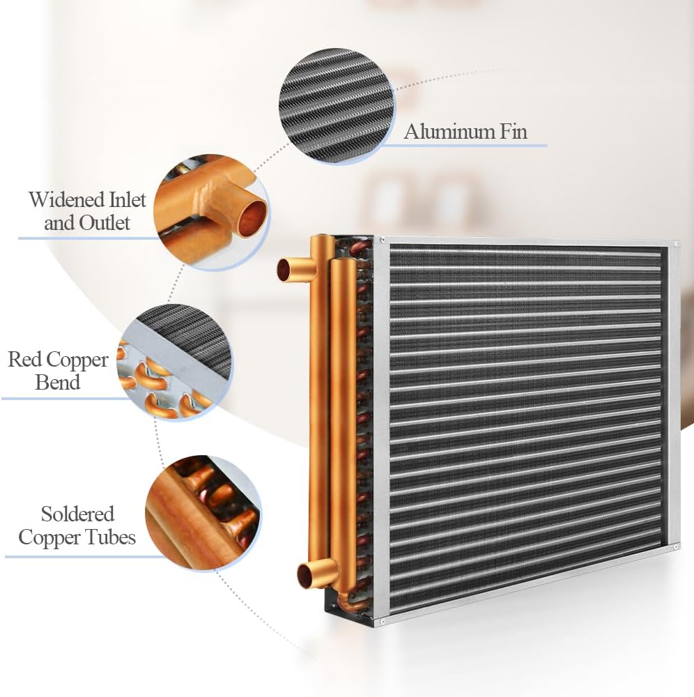
If you’ve got a cast iron boiler heating your home through baseboard or radiators — hot water circulating through a closed loop — you’ve probably got a room or space that loop doesn’t reach. A detached garage, a bonus room above the garage, a workshop, a basement finish. The baseboard approach won’t work there, but you don’t want a second heating system. That’s exactly the problem a water-to-air heat exchanger solves. The exchanger is essentially a coil of copper or aluminum fins that mounts inside an air handler or duct: your boiler sends hot water through it, a blower fan pushes air across those hot fins, and out comes warm forced air — same heat source, different delivery. This article walks through how to size that exchanger correctly, what water temperature your boiler actually needs to deliver, how to pipe the new zone without destabilizing what’s already working, and what the real installers have figured out the hard way.
Why BTU Ratings on Heat Exchangers Are Only Half the Story
Here’s the trap that catches almost everyone the first time: a water-to-air heat exchanger’s nameplate BTU rating assumes a specific inlet water temperature, and that number is almost always higher than what a typical residential boiler runs at.
The ASHRAE Handbook’s chapter on coils and heat exchangers is explicit on this point — coil output is a function of the log mean temperature difference (LMTD) between the water and the incoming air. Drop the water temperature, and you drop the output, non-linearly. HPAC Magazine’s coverage of water-to-air coil performance reinforces the same finding in contractor-facing language: a coil rated at a given BTU figure at 180°F supply water might deliver 60–70% of that figure at 140°F supply, and less still at 120°F.
This isn’t theoretical. Aggregated owner reports and installer documentation confirm it in the field. One documented case — cited in product review threads and installer forums — involved a nominally 50,000 BTUH hanging unit heater connected to a tankless water heater running at 140°F. Measured output: approximately 25,000 BTUH. That’s a 50% haircut. If you’re sizing a space based on the nameplate number and your boiler runs a low-temperature setpoint, you will undersize the zone.
The practical rule:
- Exchanger nameplate ratings are typically published at 180°F supply / 60°F entering air
- At 140°F supply, derate to roughly 55–65% of nameplate output
- At 120°F supply (common in radiant or mod-con systems), derate to 40–50%
Cast iron boilers running standard residential heat curves — a Weil-McLain Gold Series or Burnham ES2 set at 180°F — will meet nameplate conditions. If you’re on a lower setpoint for radiant or you’re pulling from a water heater, size up by 40–60% and don’t apologize for it.
Sizing the Exchanger and the Circulator Together
Heat Exchanger Sizing
Start with your heat loss calculation for the target space, not the exchanger catalog. Per ASHRAE fundamentals, Manual J (ACCA) or a simplified heat loss estimate for a detached garage in a cold climate will typically land between 20,000 and 60,000 BTUH depending on insulation and square footage. Once you have that number, apply the derate for your actual supply temperature before selecting the exchanger size.
By the Numbers
| Supply Water Temp | % of Nameplate BTU Delivered | Example: 50k BTU Exchanger Actual Output |
|---|---|---|
| 180°F | 100% | 50,000 BTUH |
| 160°F | ~80% | ~40,000 BTUH |
| 140°F | ~55–60% | ~27,500–30,000 BTUH |
| 120°F | ~40–45% | ~20,000–22,500 BTUH |
Approximate values based on ASHRAE coil performance curves; actual output varies by coil design and airflow.
A 12×15 exchanger (roughly the coil face dimensions used in mid-range residential and light commercial units) is typically rated at 60,000–100,000 BTUH at 180°F. For the average insulated garage zone on a 180°F cast iron boiler, that range covers most scenarios. For a 140°F source, step up one size class.
Circulator Sizing
A dedicated zone circulator is non-negotiable. You’re not piggybacking this on an existing zone pump.
The key variable is head pressure — the resistance the pump has to overcome based on pipe diameter, run length, fittings, and elevation change. Contracting Business’s coverage of hydronic zoning strategies notes that most residential zones run 8–15 feet of head at design flow, but longer loops with elevation gain can push well above that.
Real-world installer data is instructive here: a documented installation on a 350-foot outdoor wood boiler loop with significant elevation gain used a circulator pump in the Grundfos UPS26-99FC class and handled the head requirement. That’s a meaningful data point — the UPS26-99FC is a workhorse single-speed pump that many contractors default to for residential zones, and it performs well up to roughly 18–20 feet of head at typical hydronic flow rates (2–4 GPM for a residential heat exchanger zone).
However, if your run exceeds 150 feet or has more than 10 feet of vertical lift, review the pump curve before committing. The UPS26-99FC may get you there, but longer or higher-elevation runs may require a pump in the UPS26-116F class or a variable-speed ECM pump. Pull the manufacturer’s pump curve and plot your estimated system curve — it takes ten minutes and saves a callback.
Copper porting: For a 12×15 heat exchanger, ¾-inch copper supply and return connections are standard. The exchanger’s inlet/outlet ports will dictate this, but most units in the 40,000–100,000 BTUH range use ¾-inch NPT fittings. Sweat your zone isolation valves and balancing valve at the same size; stepping down to ½-inch anywhere in the loop will create unnecessary head loss and restrict flow.
Piping the Zone Without Destabilizing What You Have
Connection Strategy
The cleanest connection point is a dedicated tee off the main supply and return headers near the boiler — the same approach used for any new hydronic zone. Install a zone valve (24V actuator type is most common) or a dedicated circulator with a check valve on the supply side. Run your zone out to the exchanger, return it to the main return header, and wire the zone valve or circulator to your thermostat.
This Old House’s guidance on cast iron boiler zones emphasizes proper air elimination on new branches — install an auto air vent at the exchanger’s high point, and purge the zone thoroughly before commissioning. A new water-to-air zone that won’t heat is almost always an air lock, not a pump or valve failure.
Expansion Tank: The Step Everyone Skips
Adding a new zone increases the total system water volume, and that matters for your existing expansion tank. The expansion tank — the pressurized bladder or diaphragm tank connected near the boiler — is sized to accommodate the change in water volume as the system heats from fill temperature to operating temperature. Undersized expansion tanks cause repeated pressure relief valve discharge and chronic system issues.
ACHR News has covered expansion tank sizing when adding hydronic zones: the rule of thumb is approximately 1 gallon of expansion tank acceptance volume for every 10–12 gallons of added system water volume. A new heat exchanger zone with 50–75 feet of ¾-inch copper adds roughly 1.5–2 gallons of water. That’s marginal on most properly sized existing tanks — but if your current tank is already borderline, add a small supplemental tank on the new zone’s return rather than retrofitting the primary.
Check your existing tank’s pre-charge pressure (should match your cold fill pressure, typically 12–15 PSI) and its acceptance volume spec before assuming you’re fine.
Glycol in an Unheated Space Loop
If the exchanger loop passes through an unheated garage or shop where temperatures can drop below freezing, glycol is not optional. ASHRAE recommends propylene glycol (food-safe grade) for systems where freeze protection is required and system contact with potable water is possible. A 30% propylene glycol mix provides protection to approximately -4°F; 40% gets you to -15°F.
Important: adding glycol to the entire system is often impractical if the boiler serves other zones. In that case, install a plate heat exchanger as a buffer between the boiler loop and the glycol-filled exchanger zone. This is a cleaner solution for multi-zone systems where some zones are indoors and some aren’t — it isolates the glycol loop entirely.
Shipping Damage, Inspection Protocol, and Commissioning Checklist
Across aggregated buyer reports, shipping damage on water-to-air heat exchangers is a recurring minor theme. Fins bent in transit are the most common issue, followed by damaged coil connections. The good news: prompt inspection (within the carrier’s damage window, typically 48–72 hours of delivery) and documentation via photos has resulted in straightforward replacements from major distributors in documented cases.
Before installation, inspect:
- All coil fins for damage or compression (minor fin straightening is acceptable; crushed fin sections are not)
- Copper headers for cracks or dents at connection points
- Casing integrity if the unit ships assembled
Commissioning checklist:
- Pressure test the zone to 30 PSI (hold 15 minutes) before opening to the main system
- Purge zone from supply to return — bleed until water flows bubble-free
- Check auto air vent operation at the exchanger high point
- Verify zone valve opens fully at thermostat call (use a clamp meter to confirm actuator draw)
- Measure supply and return water temperature at design conditions — the delta-T should be 15–25°F at design flow
- Verify blower fan speed and airflow direction relative to coil face
Frequently Asked Questions
What supply water temperature do I need to achieve the rated BTU output from a water-to-air heat exchanger? Nameplate ratings are published at 180°F supply water and 60°F entering air. For full rated output, your boiler setpoint needs to be at or near 180°F. At 140°F supply, expect 55–65% of nameplate output. Size accordingly.
Can I use a standard UPS26-99FC circulator pump for a heat exchanger zone or do I need higher head capacity? For runs under 150 feet with modest elevation change (under 10 feet), the UPS26-99FC handles most residential water-to-air zones comfortably. Documented installations on 350-foot outdoor loops with elevation gain have succeeded with this pump class, but verify against the manufacturer’s pump curve for your specific system. Longer runs or greater lift may require the UPS26-116F or a variable-speed ECM alternative.
Will adding a water-to-air zone affect the pressure balance in my existing expansion tank setup? Yes, if the added water volume is significant. A typical residential heat exchanger zone adds 1.5–3 gallons of system water. Most properly sized existing expansion tanks absorb this without issue, but verify your tank’s acceptance volume and pre-charge pressure. If the system is already prone to pressure relief valve discharge, add a supplemental expansion tank on the new zone return.
Do I need to add glycol to a heat exchanger loop that runs through an unheated garage or shop? Yes, if any portion of the loop is exposed to freezing temperatures. Propylene glycol at 30–40% concentration is the standard approach. For multi-zone systems, isolate the glycol loop using a plate heat exchanger buffer rather than contaminating the entire boiler system.
How do I connect a heat exchanger zone to my existing cast iron boiler without disrupting other zones? Tee off the main supply and return headers with isolation valves on the new branch. Install a zone valve or dedicated circulator with check valve, wire to a thermostat, and purge the new zone independently before opening it to system pressure. Other zones remain operational throughout if you sequence the isolation valves correctly.
What size copper porting and fittings do I need for a 12×15 heat exchanger installation? Standard for a 12×15 unit in the 60,000–100,000 BTUH class is ¾-inch NPT inlet and outlet ports. Run ¾-inch copper supply and return throughout the zone; don’t step down to ½-inch. Install a balancing valve on the return to allow flow adjustment at commissioning.
The decision rule: If your cast iron boiler runs at 180°F setpoint and your new space requires under 60,000 BTUH of heat, a direct water-to-air zone with a UPS26-99FC circulator and a standard expansion tank check is a clean, low-risk addition. If your source water is below 160°F, or your run exceeds 150 feet, or the loop passes through freezing space — size up the exchanger, re-evaluate the pump curve, and isolate the glycol loop via a buffer plate. Each of those variables is a branch point, not a showstopper. Work through them in order and the math holds.