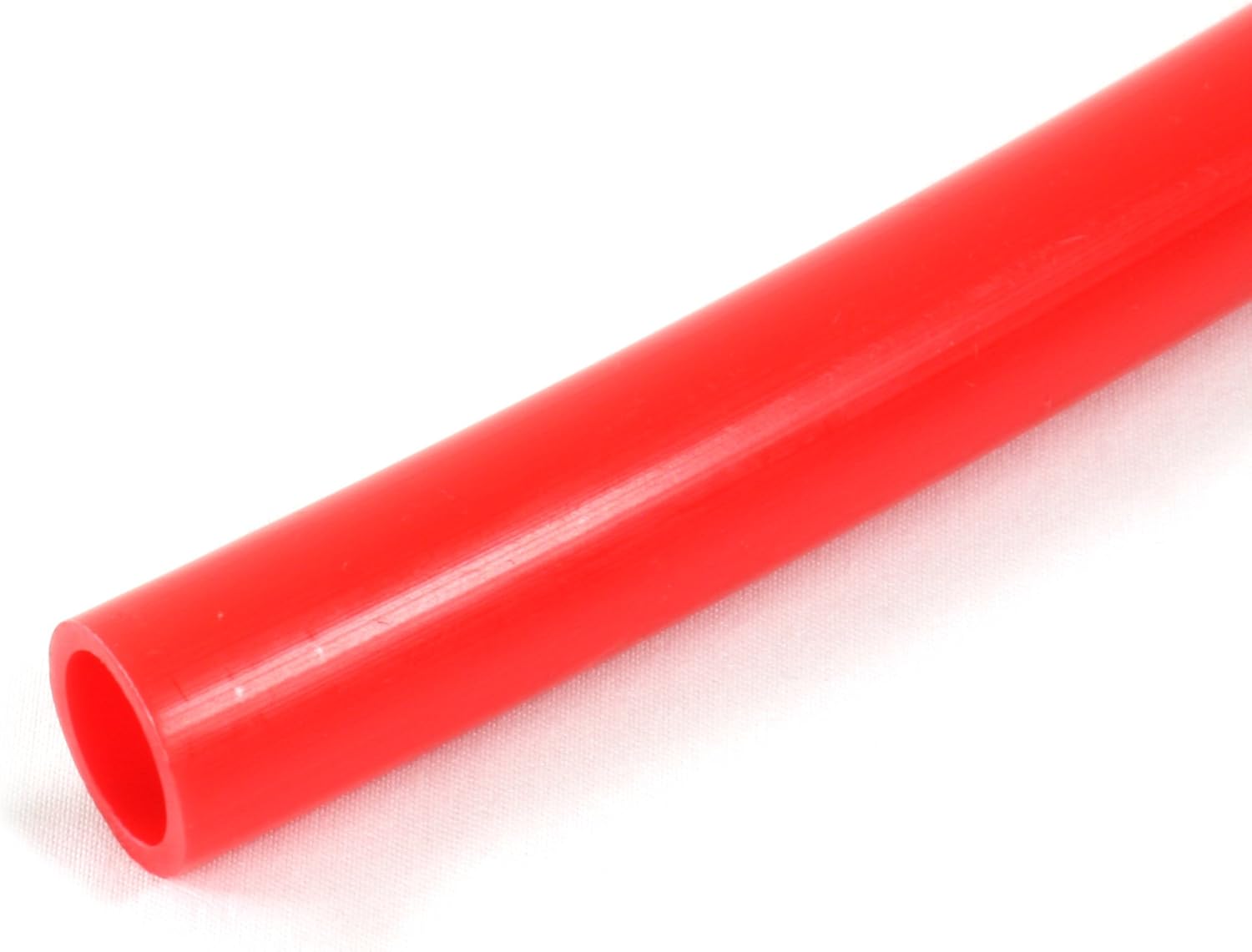
Radiant floor heating works by running warm water through a network of flexible plastic tubing embedded in or stapled beneath your floor — the floor itself becomes a large, low-temperature heat emitter that warms a room from the ground up. Cast iron boilers are a natural partner for this setup: their substantial thermal mass (the heat stored in the iron itself) smooths out water temperature swings and pairs well with the slow, steady heat release that radiant systems demand. But connecting those two components correctly requires making two decisions that practitioners sometimes underweight until a callback forces the issue: what type of PEX tubing to specify, and how to balance flow across multiple zones at the manifold. This article gives you the framework for both, with the tradeoffs named explicitly so you can defend your spec sheet on any job.
Why Oxygen Barrier PEX Is Non-Negotiable with Cast Iron
PEX (cross-linked polyethylene) tubing comes in three production variants — PEX-A, PEX-B, and PEX-C — each describing the manufacturing method used to cross-link the polymer chains. All three are widely used in plumbing and hydronic work. But in a closed-loop hydronic radiant system connected to a cast iron boiler, the production method is secondary to a more urgent question: does the tubing have an oxygen diffusion barrier?
Here’s the physics. Polyethylene is slightly oxygen-permeable. At radiant system operating temperatures (typically 90°F–140°F supply in low-temperature zones), dissolved oxygen migrates through the tube wall and into the system water over time. Cast iron, unlike copper or stainless, corrodes readily in the presence of dissolved oxygen. Per ACHR News’s 2024 analysis of hydronic corrosion failure patterns, oxygen ingress through non-barrier PEX is one of the most consistent upstream causes of premature cast iron section pitting and magnetite sludge accumulation — both of which accelerate pump wear and reduce heat exchanger efficiency well before the boiler reaches its design life.
The fix is straightforward: specify EVOH-barrier PEX (ethylene vinyl alcohol copolymer, a thin oxygen-blocking layer co-extruded around the PEX tube). DIN 4726 is the German standard most North American manufacturers reference for barrier performance — it limits oxygen permeation to ≤0.1 g/m³·day at 40°C. Most reputable barrier PEX products from Uponor, Rehau, and Watts Radiant meet or exceed that threshold.
The tradeoff to name explicitly: EVOH-barrier PEX costs roughly 15–25% more per linear foot than non-barrier PEX-B at 2026 distributor pricing. On a 1,500 sq ft slab-on-grade installation requiring ~4,500 linear feet of ½” tubing, that premium runs $300–$600 in material cost. Compared to the labor and material cost of a section replacement on a Burnham ES2 or Weil-McLain Gold Plus — easily $1,200–$2,500 once the system is drained, the section sourced, and the boiler resealed — the barrier spec pays back in the first prevented failure. Document this math in your project record. If a client or GC pushes back on tubing cost, this is the number you cite.
One more wrinkle: PEX-A (Uponor AquaPEX, Rehau RAUPEX) is frequently specified for radiant because its superior flexibility reduces the minimum bend radius and makes tight slab loops easier to install without kinking. PEX-B (Viega PEX, Watts Radiant) is stiffer but holds roundness better under compression fittings. Both are available with EVOH barriers; the barrier layer is independent of the production method. Don’t let a supplier conflate “PEX-A” with “barrier PEX” — they’re separate attributes.
Manifold Selection: Matching Port Count, Flow Rate, and Material to the Job
The manifold is the distribution hub — a supply-and-return header that splits the boiler’s single circuit into individual zone loops, each with its own flow path and (ideally) its own flow control. Choosing the wrong manifold is the fastest way to create an unbalanced system where one room runs at 75°F and the adjacent room stalls at 62°F despite identical thermostat setpoints.
Port Count and Loop Length Discipline
The Radiant Panel Association’s Design Manual (7th Edition) recommends individual loop lengths no longer than 300 feet for ½” tubing at typical radiant flow velocities (0.5–1.0 ft/s). Longer loops create disproportionate pressure drop, starving distant zones. If your floor plan pushes a single loop beyond 300 feet, split it into two ports rather than trying to compensate with flow rate. The math:
By the numbers:
- ½” PEX @ 0.5 gpm: pressure drop ≈ 1.5–2.0 ft head per 100 ft of loop
- 300 ft loop: ~4.5–6.0 ft head total — manageable for a standard zone pump
- 400 ft loop: ~6.0–8.0 ft head — begins exceeding small circulator curves; flow rates drop unpredictably
Size your manifold port count around loop discipline, not around room count. A 1,200 sq ft addition with three rooms may need five or six ports if the floor plan forces long diagonal runs.
Brass vs. Stainless Manifold Bodies
Manifolds come in two primary materials: brass and stainless steel.
Brass manifolds (Watts Radiant, Caleffi, generic imported assemblies) are the dominant mid-market choice. They’re compatible with standard hydronic water chemistry and work fine in closed systems treated with a corrosion inhibitor (Fernox F1 or Sentinel X100 are widely specified). The concern with brass in cast iron systems isn’t the manifold itself — it’s that brass fittings in contact with under-treated system water can contribute minor amounts of copper and zinc ions, which can plate onto cast iron surfaces over time. Properly inhibited water chemistry eliminates this as a practical concern.
Stainless steel manifolds (Viega ProRadiant, Uponor EP Manifold) cost more — typically 20–40% at distributor — but are the spec-safe choice for systems where water chemistry discipline can’t be guaranteed (rental properties, multi-family where treatment intervals are inconsistent, or historic buildings with mixed metallurgy). HPAC Engineering’s 2023 review of multi-zone commissioning practices notes that stainless manifolds also show better long-term thread integrity when loops are removed and reconnected during phased renovations.
Decision rule: If you’re specifying for a careful owner-occupant who will maintain a water chemistry log and annual inhibitor top-ups, brass is a legitimate value choice. If you’re specifying for a property manager with eight units and no HVAC maintenance contract, spend the delta on stainless.
Integrated Flow Meters vs. Manual Balancing Valves
Every serious manifold specification decision bottoms out here. You have two balancing approaches:
Manual balancing valves (typically Euroconus or compression ball valves at each port) rely on the installer throttling each loop by feel or by temperature differential measurement at commissioning. This works — experienced installers can get a system reasonably balanced this way — but it requires skill, time, and a return visit if the first-season performance data shows drift.
Integrated flow meters with adjustment knobs (standard on Viega ProRadiant, Uponor EP, Watts Radiant UFH series at the mid and upper tier) let the installer set a target gpm for each loop — typically 0.5–0.75 gpm for ½” tubing — and read actual flow through a sight glass or rotameter. This turns balancing from a judgment call into a measurement task. The ASHRAE 2023 HVAC Systems and Equipment Handbook is explicit that flow-meter manifolds are the preferred approach for systems with more than four zones because the interaction effects between simultaneous zone calls make manual balancing increasingly unreliable as zone count grows.
The cost tradeoff: A 6-loop brass manifold with manual valves runs roughly $180–$280 at distributor (SupplyHouse.com and eComfort pricing as of mid-2026). A 6-loop Viega or Uponor manifold with integrated flow meters runs $420–$650. On a $12,000 commercial-grade installation with a Burnham Commercial or Crown Phönix at the head, the manifold delta is noise. On a $2,200 entry-level residential job with a Burnham ES2, it deserves an honest conversation with the homeowner about payback in service calls avoided.
Connecting to the Cast Iron Boiler: Supply Temperature and Near-Boiler Piping
Cast iron boilers are not inherently low-temperature devices — most are designed to run at 160°F–180°F supply for baseboard or radiator systems. Radiant floors, by contrast, typically call for 90°F–120°F supply water to avoid uncomfortable floor surface temperatures and thermal stress on floor materials. That gap requires an injection mixing loop or a motorized mixing valve (Caleffi, Taco, Watts) to temper supply water before it reaches the manifold.
Two points practitioners sometimes miss:
-
Return water temperature protection. Cast iron boilers are vulnerable to flue gas condensation when cold return water (below ~130°F) hits the heat exchanger surfaces — this is the same condensation mechanism that causes section cracking in non-condensing cast iron. A properly sized mixing valve maintains return temperatures above the dew point threshold. Watts Water Technologies’ TB-104 technical bulletin specifies a minimum return temperature of 140°F for most non-condensing cast iron applications. Your mixing loop design must guarantee this under all zone-off conditions, not just full-load.
-
Hydraulic separation. When multiple zone pumps operate off the same boiler, flow interference creates pressure imbalance that manifests as short-cycling and noise. A low-loss header or hydraulic separator (Caleffi Discal, Taco 4900 series) between the boiler circuit and the zone manifold circuits eliminates this interaction. On any system with more than two radiant zones fed from a single cast iron boiler, hydraulic separation should be treated as required, not optional.
If X, Then Y: Your Decision Rules
Here’s where the analysis compresses into field-ready logic:
-
If the boiler has any ferrous (iron or steel) components in the heat exchanger — which is every cast iron boiler on this site — then specify EVOH-barrier PEX only. No exceptions. Document it in the spec.
-
If the system has four or fewer zones with loops under 250 feet each, a brass manifold with manual balancing valves is defensible and cost-appropriate.
-
If the system has five or more zones, mixed loop lengths, or a property management ownership structure, specify a stainless manifold with integrated flow meters. The commissioning accuracy and long-term serviceability justify the premium.
-
If supply water temperature from the boiler exceeds 130°F (standard for any non-condensing cast iron unit), install a motorized mixing valve or injection mixing loop before the manifold — and verify return temperature protection at all partial-load conditions.
-
If the project budget is tight and you need to make one upgrade, make it the oxygen barrier PEX. The corrosion it prevents is the failure mode that kills cast iron boilers early, and it’s the one most invisible to the homeowner until sections are already pitted.
Water chemistry treatment — inhibitor type, concentration, and annual verification — sits on top of all of the above. Viega’s installation manual, the Radiant Panel Association’s design guide, and Fernox’s product documentation all converge on the same point: barrier PEX plus inhibited water chemistry plus proper mixing valve staging is the three-part combination that routinely takes a cast iron radiant system to its 25-year design life. Miss any one of the three and you’re managing failure modes instead of running a system.