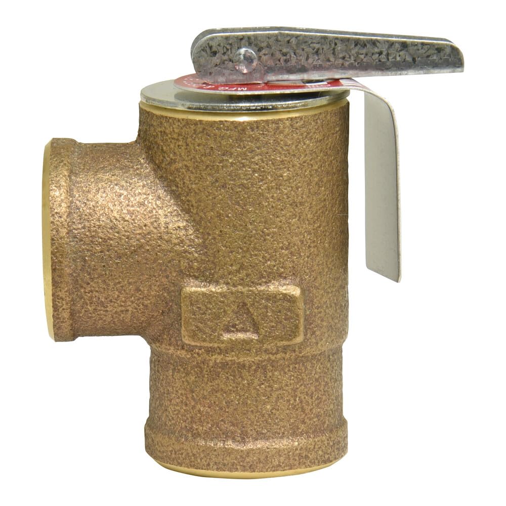
Every hydronic heating system — the kind that circulates hot water through pipes to radiators or baseboard heaters — operates under pressure, typically somewhere between 12 and 25 PSI (pounds per square inch) during normal operation. That pressure is intentional and useful: it keeps water liquid above 212°F and pushes fluid through the circuit reliably. But if a control fails, a circulator locks up, or an expansion tank waterlogged beyond recovery can no longer absorb thermal expansion, pressure can climb fast. The pressure relief valve (PRV) — a spring-loaded safety device threaded directly into the boiler — is the last mechanical line of defense before that situation becomes a rupture. It opens automatically at a set threshold, dumps water to drain, and drops system pressure before structural damage occurs. This article explains why the 30 PSI rating and ASME listing on residential hydronic PRVs are not arbitrary numbers, how to select the right valve for the specific system in front of you, and what installation details separate a compliant, reliable installation from a liability waiting to happen.
| EDITOR'S PICKApollo Valves VLV | Mid-tierApollo Valves Relief Valve | Budget pickApollo Valves Water Relief Valve | |
|---|---|---|---|
| Pressure | 50 PSI | 30 psig | 30 psig |
| Size | 3/4" | — | 3/4" |
| Material | BRZ | — | — |
| Btu Rating | — | — | 535000Btu |
| Price | $41.38 | $37.44 | $34.45 |
| See on Amazon → | See on Amazon → | See on Amazon → |
Why 30 PSI Is the Standard — and When It Isn’t
The 30 PSI set point on residential hydronic boiler relief valves is not a manufacturer convention — it’s baked into ASME Section IV, the governing code for heating boilers. Most residential and light-commercial cast iron boilers are rated for a maximum allowable working pressure (MAWP) of 30 PSI. The PRV set point must match the MAWP; it cannot exceed it. That’s the ceiling, not a suggestion.
In practice, normal residential system operating pressure runs 12–18 PSI cold, rising perhaps 3–5 PSI at operating temperature when the expansion tank is properly sized and charged. The spread between operating pressure and relief pressure — roughly 12–18 PSI of headroom — is intentional. It gives the system room to breathe across temperature swings without nuisance weeping at the valve seat.
Where things get complicated is in taller buildings. A rough rule of thumb: add 0.43 PSI of static head pressure for every foot of elevation above the boiler. A four-story building with radiators 40 feet above the boiler floor carries roughly 17 PSI of static head before the system even fires. Add normal operating pressure and you’re at 29–30 PSI cold — already brushing the relief valve’s set point. In those installations, the design pressure may need to step up to 50 PSI (using a boiler with a 50 PSI MAWP rating), which requires a 50 PSI ASME-listed PRV and a higher-rated pressure-reducing valve on the fill side. Plumbing and HVAC Magazine’s 2023 coverage of PRV selection for cast iron hydronic systems flags this tall-building mismatch as one of the most commonly under-specified items on light-commercial retrofits.
The decision rule here is straightforward: If the system static head plus normal operating pressure leaves less than 5 PSI of margin below the PRV set point, you’re not using a 30 PSI valve — you’re using a higher-rated boiler and valve combination, full stop.
ASME Listing: What the Stamp Actually Certifies
The ASME (American Society of Mechanical Engineers) stamp on a relief valve is a third-party certification that the valve has been tested and verified to open at its rated pressure, flow enough BTU/hr capacity to match the boiler’s output rating, and reseat reliably after a discharge event. That last point matters more than most installers give it credit for: a valve that opens correctly but won’t reseat fully becomes a chronic drip that corrodes the valve seat, wicks mineral deposits into the spring mechanism, and eventually fails open or closed — neither outcome is acceptable.
An unlisted valve — typically imported hardware sold at a fraction of the cost of a listed valve — may carry a label that says “30 PSI” without having been independently verified to open at that pressure under flow conditions, discharge sufficient capacity, or reseat cleanly. The Hydrolevel Corporation technical bulletin on hydronic system relief valve sizing notes that capacity (BTU/hr discharge rate) is as important as set pressure: an undersized valve that opens at the right pressure but can’t flow enough volume to relieve the boiler’s full heat output creates a runaway condition even with the valve functioning.
Every jurisdiction that has adopted the International Mechanical Code (IMC) or International Plumbing Code (IPC) — which as of 2026 covers the vast majority of U.S. states — requires ASME-listed relief valves on heating boilers. It is not optional, it is not a “best practice,” and it is the first thing an insurance adjuster looks at after a boiler-related loss.
By the Numbers: PRV Selection Checklist
| Parameter | Residential (30 PSI MAWP) | Mid-Rise / Light Commercial |
|---|---|---|
| Set pressure | 30 PSI | 50 PSI (verify boiler MAWP) |
| Minimum BTU/hr capacity | ≥ boiler gross output | ≥ boiler gross output |
| Connection size (typical) | ¾” NPT | 1” NPT |
| ASME stamp required | Yes — Section IV | Yes — Section IV |
| Test lever required | Yes | Yes |
Common Failure Modes — and What They’re Actually Telling You
A relief valve that weeps, drips, or discharges periodically is not necessarily failing — it may be doing exactly what it was designed to do, signaling a problem elsewhere in the system. The ACHR News field report on common causes of boiler relief valve weeping (2024) identifies three patterns that contractors encounter most frequently:
1. Waterlogged expansion tank. The expansion tank (a bladder- or diaphragm-type vessel that absorbs the volume increase as water heats) loses its air charge over time. When it can no longer accept expanded water volume, pressure spikes to the relief point on every heat call. The PRV weeps, the system loses a small amount of water, the auto-fill valve adds cold makeup water, and the cycle repeats — silently eroding the system and depositing minerals at the valve seat. The fix is recharging or replacing the expansion tank, not the relief valve.
2. Oversized fill pressure-reducing valve (PRV on the cold side). If the fill valve is set too high or is failing open, it can push system pressure up toward the relief threshold before the boiler even fires. Check cold fill pressure before diagnosing the relief valve.
3. Valve seat fouling from mineral deposits. Hard water systems — particularly in regions with calcium carbonate above 150 mg/L — deposit scale on the valve seat after repeated weeping events. Once the seat is fouled, the valve may weep at pressures well below its set point, or in extreme cases, may not fully open when needed. Watts Water Technologies installation instructions for the 174A series specifically recommend testing the lift lever annually to verify free operation and flush any seat buildup. If the lever is seized or the valve has been weeping for more than one heating season, replacement is the correct answer.
A note on “test and leave” practice: Many field technicians test the lift lever during a commissioning visit, confirm it moves, and call it done. That’s necessary but not sufficient. Confirm the valve reseats fully — no drip at the discharge port — before closing out the job. A valve that weeps after testing needs replacement before sign-off, not a note in the service report.
Installation Details That Codes Require (and Inspectors Check)
Correct valve selection accounts for roughly half the compliance picture. The installation itself has several requirements that are non-negotiable under ASME Section IV and most local mechanical codes:
Discharge piping to a safe point of termination. The PRV discharge outlet must be piped — full bore, no reduction in diameter, no valves, no caps — to a point of safe discharge: a floor drain, an indirect waste receptor, or to within 6 inches of the floor. The discharge pipe must be the same diameter as the valve outlet (minimum ¾”) and must be as short and straight as practical to avoid back-pressure that could prevent full valve opening. Capping the discharge port — a practice occasionally documented in failed inspections on older DIY work — creates a sealed vessel scenario. This is not a code violation in the bureaucratic sense; it is a bomb.
No isolation valve between boiler and PRV. The valve must connect directly to the boiler, with no shutoff valve in the supply line to the PRV. This seems obvious but shows up in field conditions when a previous installer added a ball valve “for serviceability.” Remove it.
Orientation. Most modern spring-loaded PRVs are rated for vertical, horizontal, or angled installation, but verify the manufacturer’s instructions — Watts, Conbraco, and Honeywell/Resideo all publish orientation allowances in their installation sheets, and they are not identical across product lines.
Matching BTU capacity to the boiler. Pull the boiler nameplate gross output — not net output, not DOE heating capacity. The PRV’s ASME-stamped BTU/hr capacity must equal or exceed that number. On a mid-size residential cast iron boiler like a Weil-McLain Gold Series running 175,000 BTU/hr gross input, a standard ¾” 30 PSI valve rated at 400,000 BTU/hr provides substantial margin. On a larger commercial section boiler in the 500,000–800,000 BTU/hr gross range, confirm the valve’s rated capacity against the nameplate rather than assuming a standard residential valve covers it.
The Decision Framework
If you’re selecting or specifying a PRV for a current job, the branching logic is this:
-
System static head + cold fill pressure leaves ≥ 5 PSI margin below 30 PSI: Standard ¾” 30 PSI ASME-listed valve, BTU capacity matched to gross boiler output, discharge piped to floor drain, no isolation valve, lever tested and reseating confirmed.
-
Static head + fill pressure within 5 PSI of 30 PSI: Do not use a 30 PSI valve. Evaluate whether the boiler itself is rated for 50 PSI MAWP; if not, the system design needs to change before the valve selection conversation.
-
Replacement on an existing weeping valve: Diagnose the root cause first. If it’s expansion tank failure or fill valve drift, replacing only the PRV solves nothing. Replace the PRV regardless — a valve that has weep-cycled through mineral-laden water has a compromised seat — but address the underlying cause simultaneously.
-
Historic or multi-family renovation with steam sections mixed into the circuit: Steam systems have entirely different PRV requirements (15 PSI MAWP maximum under ASME Section IV for low-pressure steam). Do not apply hydronic PRV logic to a steam boiler. The rated pressures, valve types, and sizing procedures are not interchangeable.
The 30 PSI rating and ASME listing on a hydronic boiler PRV represent the minimum acceptable specification for a reason: they are the threshold below which the last safety device on the system cannot be relied upon to work. That’s not a marketing claim — it’s the outcome of a century of boiler incident data encoded into the ASME code. Spec accordingly.