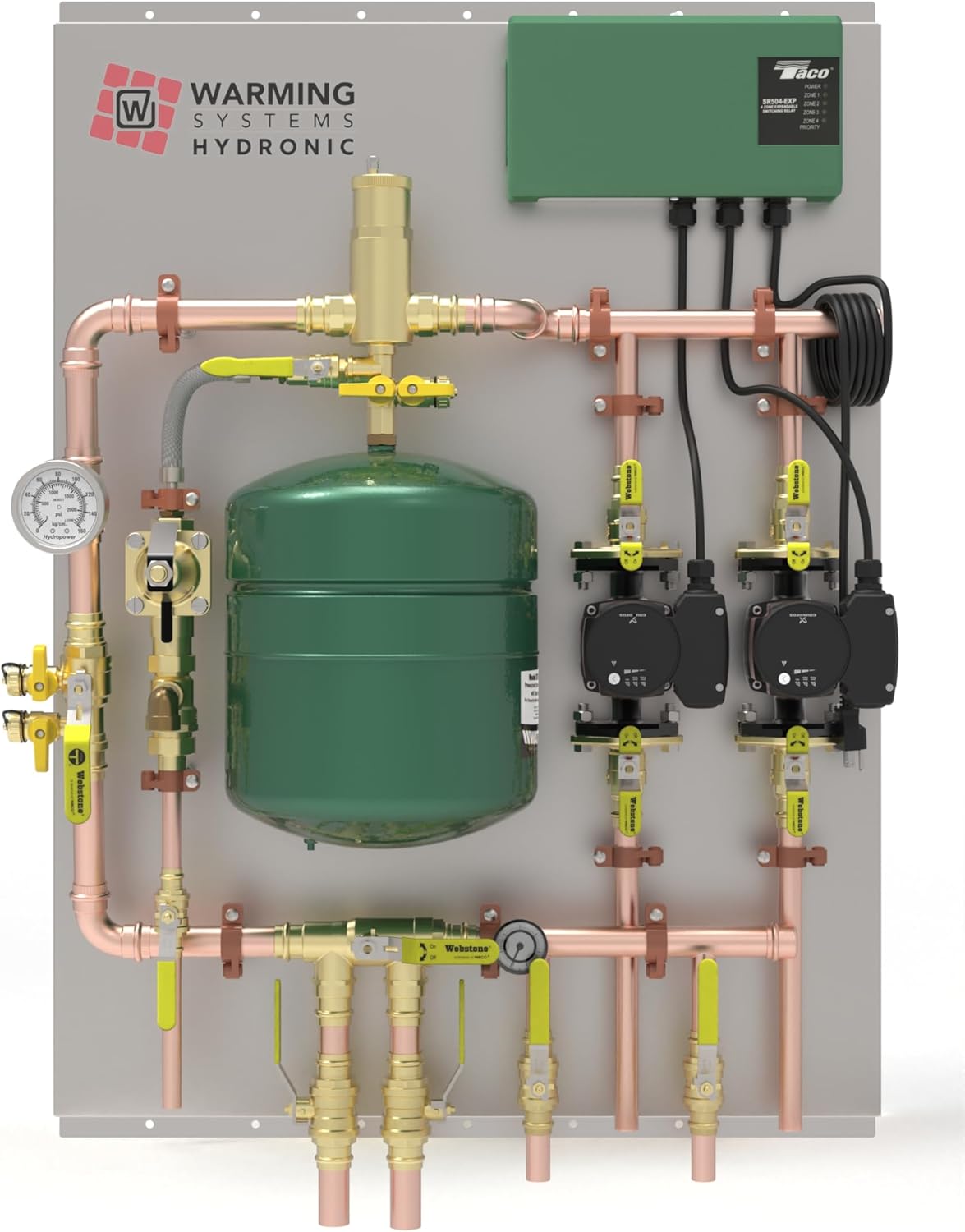
A hydronic heating system moves hot water through pipes to radiators or baseboard convectors to heat a building. Like any plumbing loop, it is susceptible to one persistent enemy: trapped air. Air pockets block water flow, cause gurgling or banging noises, create cold spots in radiators, and force circulator pumps to work harder than they should. Manual bleeding — opening small valves on each radiator to release trapped air by hand — is the traditional fix, but it is time-consuming and easy to neglect. An automatic air vent valve (also called an auto vent or float vent) does the same job continuously and without anyone touching it. It is a small float-operated device that screws into a tapping in the piping, opens when air is present, releases the air, and closes when water returns. For a part that typically costs less than a service call, it does meaningful work.
This article covers where automatic air vents belong in a cast iron boiler system, how to size and specify them, what the failure modes look like, and how they interact with other system components — expansion tanks, circulator placement, oxygen-barrier tubing — that affect long-term air management. If you are commissioning a new system, troubleshooting a chronic air problem, or evaluating a budget-friendly option like the Saillong automatic air vent valves, the decision framework below applies.
| EDITOR'S PICKHydronic Radiant Heat Control P… | Mid-tierUpgrade SR501-4 Switching Relay | Budget pick555-050RP Zone Valve Power Head… | |
|---|---|---|---|
| Type | Control Panel | Switching Relay | Zone Valve Head |
| Zones | 2 | 1 | — |
| Voltage | — | 24V | 24V |
| Compatibility | — | Taco SR501 | Taco 556/570 |
| Included Parts | ✓ | ✗ | ✗ |
| Warranty | — | — | 3-Year |
| Price | $3,175.00 | $72.59 | $59.15 |
| See on Amazon → | See on Amazon → | See on Amazon → |
How Automatic Air Vents Actually Work — and Why They Matter More Than You Think
The physics is simple. Air in a hydronic loop is less dense than water, so it migrates to the highest points in the system and to any low-velocity zones where it can accumulate rather than being swept along by flow. A float-type auto vent contains a small chamber with a buoyant float. When water fills the chamber the float rises and closes a needle valve. When air displaces water in the chamber the float drops, the needle opens, and air escapes to atmosphere. The Watts Engineering Data on float-type air vents (referenced in ASHRAE’s HVAC Systems and Equipment handbook) notes that this cycle can repeat thousands of times over a system’s life without wearing out the seat — provided the needle and seat are metal, not plastic.
That material distinction matters on cast iron boiler systems specifically. Cast iron boilers run at higher mean water temperatures than modern condensing equipment — typically 160°F to 200°F operating range — and the float mechanism must tolerate sustained heat without distortion. Brass-bodied auto vents with stainless or brass internal components are the standard for this application. Reviewers of the Saillong automatic air vent valves consistently call out the all-brass construction as a reason they selected the product over cheaper plastic-bodied alternatives, and no reviewer reports leaking or venting failure after installation in real multi-zone systems.
By the numbers — air and hydronic systems:
- Water at 180°F holds roughly 40% less dissolved oxygen than at 60°F, meaning air released at the boiler tends to accumulate near the heat exchanger first.
- A single ½-inch air pocket in a 1-inch supply main can reduce zone flow by 15–25% depending on system pressure (per ASHRAE hydronic system commissioning guidance).
- Most residential auto vents are rated to 150 PSI and 240°F — well above the operating envelope of any residential cast iron boiler.
Where to Install Automatic Air Vents on a Cast Iron Boiler System
Placement is not arbitrary. Air accumulates predictably, and your auto vent locations should map to those accumulation points.
The primary location: the system’s highest point. On a typical residential system with the boiler in the basement and baseboard convectors on upper floors, the highest point is usually the supply manifold or the top of a riser feeding an upper-floor zone. This is where a micro-bubble separator or a simple tee with an auto vent belongs. If your near-boiler piping includes a Spirovent or Caleffi Discal air separator, you may already have an integral auto vent at that device — check before adding redundant ones.
Zone manifolds. On multi-zone systems with a dedicated supply and return manifold (common in radiant floor and multi-baseboard installations), each zone’s supply branch can trap air independently — especially if zones run at different temperatures or duty cycles. One auto vent at the top of each zone manifold loop or at each zone’s highest point is the standard approach. Saillong reviewers specifically call out five-zone systems where this configuration resolved persistent cold-zone complaints.
Individual radiators and convectors. Traditional cast iron radiators have manual bleed valves at the top for a reason — that is where air goes. Replacing a manual bleed valve with a 1/8-inch auto vent is a legitimate upgrade, particularly in older homes where the homeowner is not comfortable doing seasonal bleeds. The 1/8-inch male NPT thread is the near-universal standard for these tappings in North American residential equipment.
What to avoid. Do not install auto vents at low points in the system — they will never see air and the float mechanism may gum up from sediment. Do not install them downstream of a circulator discharge on a high-velocity line; the turbulence can hold the float partially open and cause chronic weeping. The ACHR News coverage of hydronic commissioning callbacks consistently names improper auto vent placement as a contributing factor in systems that “just keep needing to be bled.”
The Oxygen-Barrier PEX Caveat — and the Expansion Tank Connection
If you are working with a system that uses oxygen-barrier PEX (EVOH-layer tubing that limits oxygen diffusion into the loop), you may have been told that air management is a non-issue. That is an overstatement. As covered in related content on this site, oxygen-barrier PEX reduces ongoing oxygen ingress significantly compared to standard PEX or older rubber tubing — but it does not eliminate it, and it does nothing about the air already dissolved in the fill water at commissioning, air introduced during service events, or air drawn in through a failing component.
That last point deserves emphasis: expansion tank bladder failure is a common and underdiagnosed source of chronic air problems. An expansion tank — the pressurized tank that absorbs the volume change as water heats and cools — contains a rubber bladder separating the air charge from the system water. When that bladder ruptures, the air charge is released directly into the system loop. The result is a hydronic loop that seems to need constant bleeding even after you have bled every radiator and convector. Building Green’s hydronic system best practices documentation specifically flags bladder failure as a root cause to rule out before concluding that an auto vent installation has failed. If you have auto vents installed and the system keeps developing air pockets, check expansion tank pre-charge pressure (should match static fill pressure, typically 12 PSI at cold) before assuming the vents are at fault.
Water chemistry compounds the issue. Systems with elevated dissolved mineral content or pH outside the 7.5–8.5 range recommended by inhibitor manufacturers like Fernox and Sentinel can experience accelerated corrosion that generates hydrogen gas — a non-condensable gas that behaves like air in the system but cannot be managed by oxygen scavenging additives. Plumbing and HVAC Magazine’s coverage of inhibitor chemistry notes that hydrogen generation from iron/water reactions is most aggressive in systems that cycle frequently with fresh (unprotected) fill water. If your system needs repeated bleeding and the water tests acidic, the solution is a proper inhibitor charge, not more auto vents.
Specifying for Multi-Zone and Commercial Applications
For contractors and building engineers specifying systems with more than four zones or with commercial cast iron equipment (Burnham Commercial, Peerless MI Series, Crown Boiler Phönix), the auto vent question scales up but the logic stays the same. Larger systems benefit from a staged approach:
- Primary air separator at the boiler — a properly sized Spirovent, Caleffi, or equivalent installed on the system supply at the point of lowest solubility (highest temperature, lowest pressure). This is your first-line air removal device.
- Auto vents at zone manifold high points — particularly critical in systems where zones can be isolated by zone valves and air can become trapped when a zone is off.
- Manual bleed valves retained at terminal units as a backup — auto vents are not infallible, and a manual valve gives the installer or homeowner a diagnostic option.
Contracting Business field reporting on hydronic commissioning consistently shows that systems commissioned with only a main air separator and no branch-level auto vents tend to generate callbacks in the first heating season, particularly on zones with long horizontal runs that pitch inconsistently.
Frequently Asked Questions
Will a bent stem on arrival mean the valve is defective, or can it be straightened? The bent pin or stem complaint in Saillong reviews is entirely a packaging issue — a flimsy paper box with no foam padding allows the protruding stem to take impact in transit. Reviewers explicitly note that a minor bend in the stem does not indicate internal damage, and that the stem can typically be straightened carefully with pliers before installation. No reviewer reports that a bent-on-arrival unit leaked or failed to vent. That said, if the bend is severe enough to prevent the cap from threading properly, treat it as a shipping damage claim.
Where exactly should I install automatic air vents on a cast iron boiler with baseboard zones? Install the primary auto vent at the highest point in the supply piping — often at a tee on the main supply riser. Add secondary vents at the top of each zone’s highest baseboard section, particularly on upper-floor zones. On near-boiler piping, a tee immediately downstream of the boiler’s supply outlet (before the first elbow) is a common and effective location.
Do I need one auto vent per zone or just at the main manifold? On systems with multiple zones at different elevations, one vent at the main manifold is not sufficient. Each zone can trap air independently. The practical answer for a four- to six-zone residential system: one quality auto vent at the main supply high point plus one at the highest point of any zone that has historically shown air problems.
Can I install an auto air vent on a system that is currently pressurized? No — not safely without isolating the tapping first. Most auto vent installations require a Schrader-type service valve or an isolation ball valve at the tapping so the vent can be installed or replaced without draining the system. If your existing tapping has no isolation valve, plan to reduce system pressure before the swap.
Why does my system keep developing air pockets even after I bleed it manually? The most common culprits, in rough order of frequency: a failed expansion tank bladder releasing its air charge into the loop; a system fill valve that is passing and introducing dissolved-air-laden fresh water; active corrosion generating hydrogen gas due to low pH or missing inhibitor; or a micro-leak on the suction side of the circulator drawing in air under negative pressure. Per ASHRAE hydronic commissioning guidance, rule out expansion tank integrity first — it is the most frequently overlooked cause.
Is the 1/8-inch thread size standard for most residential hydronic air vents? Yes. 1/8-inch male NPT is the dominant standard for automatic air vent connections in North American residential hydronic equipment, including the tappings found on cast iron radiators, baseboard convector end caps, and zone manifolds. Some manifold systems use 1/4-inch NPT tappings — verify before ordering, because the two sizes are not interchangeable.